Achieving high-quality 3D prints relies heavily on precise printer calibration. Without it, you'll encounter common issues like stringing, poor bed adhesion, and inaccurate dimensions. Calibration is the foundation for consistent, reliable, and excellent print results.
OrcaSlicer is an advanced, open-source slicing software with powerful built-in calibration tools. This guide will help you use the latest stable releases of OrcaSlicer (typically versions 2.3.0 or recent 2.3.1 nightly builds) to fine-tune your printer. We'll cover Temperature, Flow Rate, Pressure Advance, Retraction, Tolerance, Max Volumetric Speed, and Vertical Fine Artifacts (VFA) calibrations. These tests are designed to be performed in a specific order, progressively improving your print quality.
Understanding OrcaSlicer: Your Calibration Hub
OrcaSlicer offers advanced features like precise wall control, "sandwich mode" for better surface finish, "polyholes conversion" for complex geometries, and seamless integration with Klipper, OctoPrint, and PrusaLink. It provides granular control while remaining user-friendly with drag-and-drop design and pre-made printer profiles.
Accessing Calibration Tools in OrcaSlicer
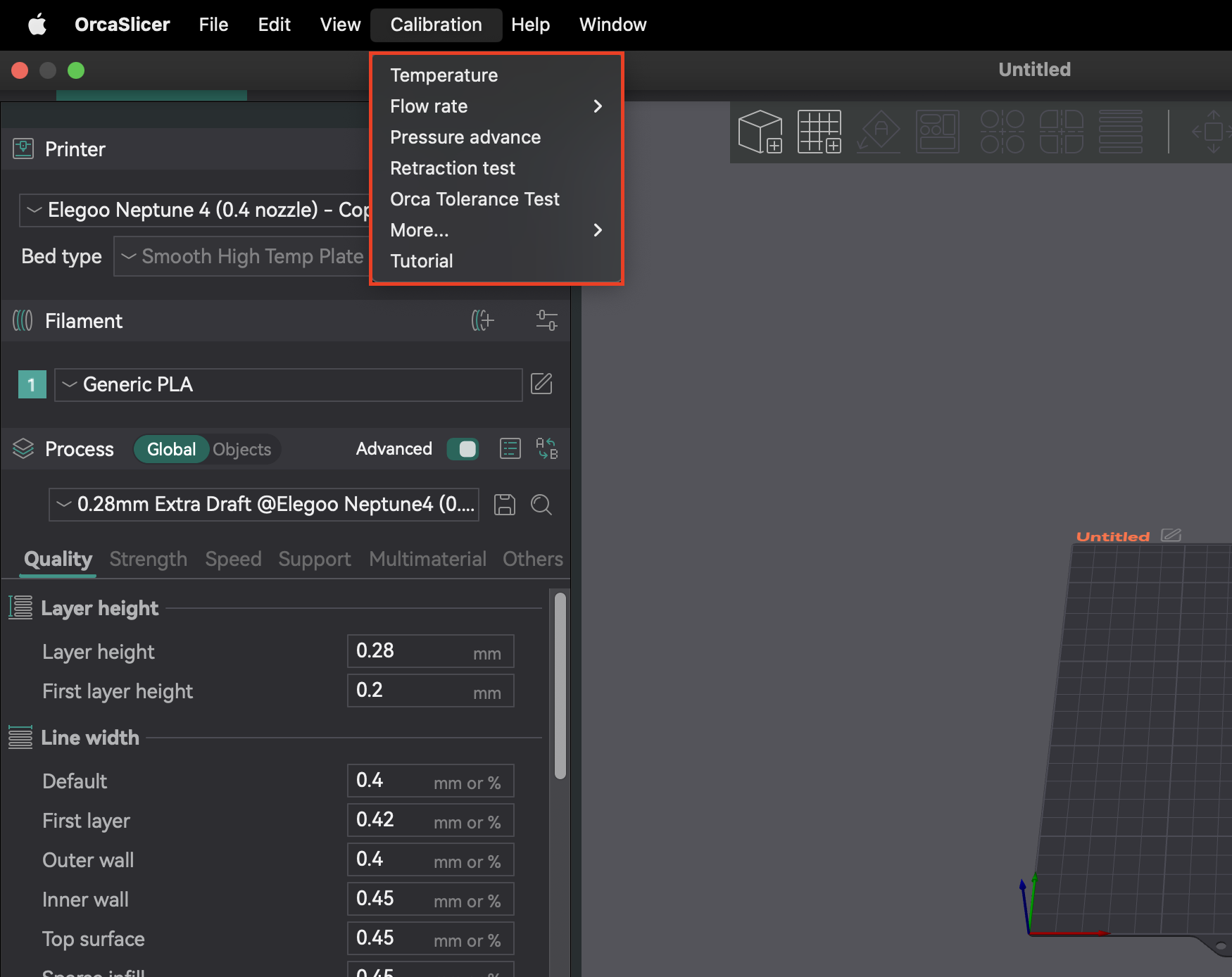
Most calibration features are in the "Calibration" menu. After completing any calibration test, always create a new project. This ensures OrcaSlicer exits calibration mode and resets parameters for your next prints.
Recommended Calibration Order
Following a specific calibration order is crucial because many settings are interdependent. Starting with foundational parameters ensures accurate results for subsequent, more nuanced adjustments. This systematic approach minimizes troubleshooting and helps you achieve better print quality efficiently.
Calibration Step | Purpose | Key Observation/Goal | Dependency/Prerequisite |
---|---|---|---|
Temperature | Optimize filament melting and bonding | Least stringing, best layer adhesion | None (assumes good mechanical setup) |
Flow Rate | Ensure correct filament extrusion amount | Smoothest top surface, no gaps or blobs | Temperature, Accurate E-steps/Rotation Distance |
Pressure Advance | Reduce artifacts from nozzle pressure fluctuations | Sharpest corners, consistent extrusion | Flow Rate, Temperature |
Retraction | Minimize stringing and oozing | Shortest length with minimal stringing | Flow Rate, Pressure Advance |
Tolerance | Accurately reproduce model dimensions | Optimal fit between printed parts | All previous extrusion/dimensional calibrations |
Max Volumetric Speed | Determine maximum filament flow rate without issues | Highest speed before under-extrusion | Temperature, Flow Rate |
Cornering/Jerk/Junction Deviation | Reduce artifacts from sharp corners | Smoother corners, reduced ringing | Flow Rate, Pressure Advance |
Input Shaping | Reduce ringing and improve print quality | Smoother surfaces, reduced ghosting | Flow Rate, Pressure Advance |
Table 1: Recommended OrcaSlicer Calibration Order
Foundational Printer Calibration: Before You Slice
Before using OrcaSlicer's advanced tools, ensure your printer's fundamental mechanical and thermal systems are configured. These steps are often done directly on your printer's firmware or through physical adjustments, not in OrcaSlicer. Skipping them can cause persistent print quality issues.
Z-Offset Calibration: Critical for First Layers
Z-offset defines the precise distance between the nozzle and the print bed for the first layer. It's critical for bed adhesion. If the nozzle is too high, filament won't stick; too low, it can scrape the bed, cause "elephant's foot," or lead to extruder clicking.
This is primarily a printer-firmware or physical adjustment. While OrcaSlicer has a Z-offset field (under Printer presets > General tab), understand how your printer's firmware handles it. Most printers rely on firmware or physical adjustments. Always perform Z-offset calibration on your printer first. Use OrcaSlicer's setting only for minor tweaks if your printer allows slicer-defined Z-offset.
Bed Leveling: Ensuring a Perfect Foundation
A level print bed ensures consistent first layer adhesion across the entire surface. An uneven bed causes areas to stick well and others to lift. OrcaSlicer offers "Adaptive Bed Mesh" to compensate for minor imperfections by mapping the bed.
OrcaSlicer's Adaptive Bed Mesh is a software tool, not a substitute for a mechanically sound and initially leveled bed. Relying solely on software without initial manual or assisted leveling (e.g., paper method) can mask mechanical issues. If the bed is significantly warped, the mesh may struggle. First, mechanically level your bed, then set Z-offset, and finally let your printer's auto-leveling or OrcaSlicer's adaptive bed mesh fine-tune.
E-steps / Rotation Distance Calibration: The Unsung Hero
Before adjusting flow rate in the slicer, ensure your extruder's E-steps (Marlin) or rotation distance (Klipper) are calibrated. This tells your printer how much filament to push. If incorrect, your printer will extrude the wrong amount, making slicer flow calibration inaccurate. This is a printer-firmware calibration, not an OrcaSlicer setting.
Core Calibration Tests in OrcaSlicer
Once foundational printer settings are done, use OrcaSlicer's built-in calibration tests to optimize print quality.
1. Temperature Calibration: Finding Your Filament's Sweet Spot
Temperature affects how filament melts, flows, and bonds. Too low, and you get under-extrusion, poor adhesion, and weak parts. Too high, and you'll see oozing, stringing, warping, and blobs.
Accurate temperature calibration depends on prior Z-offset, bed leveling, and PID tuning. If these are off, temperature tower results can be misleading. Ensure your printer is mechanically sound and PID tuned before running temperature tests for accurate results.
Step-by-Step: Using OrcaSlicer's Built-in Temperature Tower
- Preparation: In OrcaSlicer, select your material (PLA, PETG, etc.). This sets default bed and nozzle temperature ranges. Go to "Calibration" > "Temperature." Set custom start/end temperatures (increment is fixed at 5°C).
- Printing the Tower: OrcaSlicer generates a temperature tower. Slice and print it.
- Analyzing Results: After printing, inspect each layer for stringing, layer adhesion, warping, and overhang/bridging performance. Find the temperature block with the best overall print quality and fewest defects.
- Applying Settings: Update the optimal nozzle temperature in your filament profile settings in OrcaSlicer. Save the profile and create a new project.
Temperature is filament-specific. Different brands or colors of the same filament type can have different optimal ranges. Perform this test for each new filament to build a library of fine-tuned profiles.
Troubleshooting: Common Temperature-Related Issues
- Stringing/Oozing: Often means temperature is too high or retraction settings are off.
- Poor Layer Adhesion/Under-extrusion: Nozzle temperature is often too low.
- Warping: Can be incorrect bed/nozzle temperatures or insufficient cooling.
Filament Type/Brand | Tested Temp Range | Optimal Temperature | Key Observations at Optimal Temp |
---|---|---|---|
PLA (Generic) | 190-230°C | 205°C | Minimal stringing, strong layer adhesion, good overhangs |
PETG (Prusament) | 230-250°C | 240°C | Smooth surface, no warping, good bridging |
ABS (Hatchbox) | 230-260°C | 245°C | Reduced cracking, good inter-layer bonding |
Table 2: Temperature Tower Settings & Observations
2. Flow Rate Calibration: Achieving Dimensional Accuracy
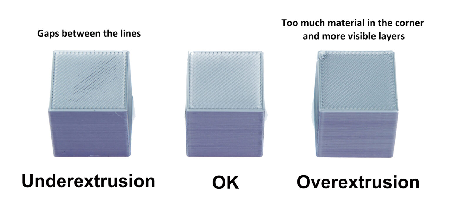
Flow rate (extrusion multiplier) controls the amount of filament extruded. It's crucial for smooth surfaces and dimensional accuracy. Too high, and you get over-extrusion: blobs, stringing, poor accuracy. Too low, and you get under-extrusion: gaps, weak adhesion, poor finish.
Flow rate calibration depends heavily on temperature and E-steps/rotation distance. If your extruder isn't calibrated, flow rate adjustments in the slicer will be inaccurate. Ensure E-steps are correct and temperature is optimal first.
Layer height and print speed can also affect optimal flow rate. If print speed limits change, re-run calibration.
Pass 1: Initial Calibration
- Creating the Test Project: In OrcaSlicer, select printer, filament, and process settings. Go to "Calibration" > "Pass 1." This generates nine blocks, each with a different flow rate modifier.
- Analyzing for Smoothest Surface: Print the project. Examine the top surfaces. Find the block with the smoothest surface, free from over-extrusion (ridges, blobs) or under-extrusion (gaps). If two are similar, choose the one with the higher flow rate.
- Calculating Flow Ratio: Calculate FlowRatio_new = FlowRatio_old * (100 + modifier) / 100. Example: 0.98 * (100 + 5) / 100 = 1.029.
Pass 2: Fine-Tuning for Perfection
- Generating Fine-Tuning Project: Create a new project. Go to "Calibration" > "Pass 2." This generates ten blocks with modifiers from -9 to 0 for precise adjustments.
- Evaluating for Consistency: Print Pass 2. Examine top surfaces for best quality, layer adhesion, and consistency. Calculate the updated flow ratio using the same formula. Example: 1.029 * (100 - 6) / 100 = 0.96726.
- Applying Settings: Save the final optimal flow ratio in your filament profile settings in OrcaSlicer.
Troubleshooting OrcaSlicer's Built-in Flow Calibration Failures: "Meta-Calibration" Guidance
You might find OrcaSlicer's built-in flow calibration results "terrible" and requiring manual intervention. This indicates a need for "meta-calibration" guidance: how to troubleshoot the calibration process itself.
- Initial Over-extrusion/Dragging: This can mean the printing temperature is too high, or E-steps/rotation distance are not calibrated. Re-check your E-steps before re-running flow calibration.
- Extruder Clicking: Often means temperature is too low for the desired flow, causing the extruder motor to skip. Increase your nozzle temperature slightly or lower your maximum volumetric speed (covered later) before re-attempting flow calibration.
- Test Inconsistency/Ambiguous Results: If calibration prints look bad but other prints are fine, consider:
- Print Speed of Test: The default speed might be too fast. Try slowing down the calibration prints.
- Line Width Settings: If line width (in Process settings) is too large for your nozzle, it can cause over-extrusion. Ensure widths are appropriate (e.g., 0.45mm for a 0.4mm nozzle).
- Subjectivity of Visual Test: Visual assessment can be subjective. For more objective results, print a single-wall cube:
- Print a single-wall cube (e.g., 20x20x20mm, 0% infill, 1 perimeter).
- Measure wall thickness with calipers.
- Calculate desired wall thickness (e.g., 0.4mm for a 0.4mm nozzle).
- Adjust flow ratio: New Flow Ratio = Current Flow Ratio * (Desired Wall Thickness / Measured Wall Thickness).
- Persistence of Issues: If flow calibration consistently fails, a preceding calibration (Temperature, E-steps/Rotation Distance, or mechanical issues) is likely still incorrect. Do not move on to Pressure Advance or Retraction until flow is reliably dialed in.
Pass | Modifier Range | Number of Blocks | Calculation Formula | Purpose |
---|---|---|---|---|
Pass 1 | +5 to -5 | 9 | FlowRatio_new = FlowRatio_old * (100 + modifier) / 100 | Initial calibration to find approximate optimal range |
Pass 2 | -9 to 0 | 10 | FlowRatio_new = FlowRatio_old * (100 + modifier) / 100 | Fine-tuning for precise optimal flow ratio |
Table 3: Flow Rate Calibration Pass 1 & 2 Summary
3. Pressure Advance Calibration: Sharpening Your Corners
Pressure Advance (PA) compensates for pressure changes in the nozzle during speed fluctuations (acceleration/deceleration). It prevents rounded corners, blobs, and "zits" by pre-adjusting extrusion to maintain uniform flow.
Always perform Pressure Advance calibration after Flow Rate calibration. If flow rate is incorrect, PA will compensate inaccurately. A stable flow rate is essential for effective PA. If your PA tests look messy, revisit Flow Rate and Temperature calibrations first.
PA values vary significantly by extruder type (Direct Drive vs. Bowden), filament type/brand, nozzle size, hotend temperature, and hardware modifications. Different materials have unique melt flow, and path length changes impact PA. This means PA often requires recalibration for different setups or materials.
Choosing Your Extruder Setup (Direct Drive vs. Bowden)
OrcaSlicer asks you to select your extruder type (Direct Drive or Bowden). PA values differ greatly due to filament path length. Bowden setups typically need higher PA values.
Methods in OrcaSlicer
OrcaSlicer offers multiple methods for Pressure Advance calibration:
- Line Method: This method helps quickly identify an optimal Pressure Advance value.
- Access: Go to "Calibration" > "Pressure Advance" > "PA Line."
- Test: OrcaSlicer generates a series of lines, each printed with an incrementally different PA value. The goal is to observe where the start and end of each line appear "cleanest" and the transition into and out of the line is sharpest, indicating the most consistent extrusion.
- Dependency: This method is sensitive to the quality of the first layer. Ensure your bed is properly leveled before performing this test.
- Pattern Method: Visual assessment for corners.
-
Access: From the "Calibration" menu, select "Pressure Advance," and then choose the "Pattern Method."
-
Test: OrcaSlicer generates a prism-like pattern. Examine for consistent extrusion quality and identify the sharpest corners with the fewest artifacts (such as gaps, bulges, or divots).
Source: obico.io
-
- Tower Method: Less sensitive to first-layer quality, but takes longer.
-
Access: Within the "Calibration" menu, select "Pressure Advance," and then choose "PA Tower."
-
Test: The software generates a tower where PA increases with height (typically 0.002 per mm for Direct Drive, 0.02 for Bowden). Examine each corner to find the height with crisp, clean corners.
-
Recommendation: Print at higher speeds (above 120 mm/s) to see PA impact under typical print conditions.
Source: ellis3dp.com
-
Applying Settings in OrcaSlicer
Once you determine the optimal PA value, open filament settings (edit icon next to profile). Enable "Enable pressure advance" and enter the value. Save the filament profile.
Method | Extruder Type | Pros | Cons | Key Observation |
---|---|---|---|---|
Line | Both | Quick, simple to test | Highly dependent on first layer quality | Cleanest line ends, sharpest point |
Pattern | Both | Visual assessment of corners, more advanced | Still somewhat dependent on first layer | Most consistent extrusion, sharpest corner with fewest artifacts |
Tower | Both | Less sensitive to first layer quality, good for high speeds | Takes more time and material | Best overall corner quality at specific height |
Table 4: Pressure Advance Method Comparison
4. Retraction Calibration: Eliminating Stringing and Oozing
Retraction pulls back filament before travel moves, creating negative pressure to prevent oozing, strings, or blobs. Key parameters are retraction length, speed, and Z-hop.
Retraction interacts with Pressure Advance. Optimal retraction helps manage physical pull-back, while PA handles pressure in the hotend. If PA isn't calibrated, retraction may struggle. The goal is the shortest length that minimizes stringing without causing clogs or "pockmarks."
If stringing persists after retraction tests, re-evaluate your Temperature and Flow Rate settings first, then Pressure Advance. These foundational settings must be correct for retraction to be effective.
Step-by-Step: Using OrcaSlicer's Built-in Retraction Test
-
Access and Configure: Create a new project. Go to "Calibration" > "Retraction Test." Configure "Start retraction length," "End retraction length," and "Step" (defaults typically 0mm, 2mm, 0.1mm). Bowden extruders generally need higher lengths (1-6mm) than direct drive (0-2mm).
-
Slicing and Printing: Slice and print the retraction tower. Ensure "Normal" Z-hop is selected. You can paint seams on inner tower sides in preview for clearer stringing observation.
Source: obico.io
-
Analyzing Results and Adjusting: Examine each notch. Find the shortest length that minimizes stringing and oozing without other issues. Example: if best quality is one notch from base with 0.1mm step, optimal length is 0.2mm. Open filament settings, "Settings overrides" tab, check "length" under retraction, input new value, and save.
Troubleshooting: Persistent Stringing, Oozing, and Nozzle Clogs
- Filament Type: Different materials ooze differently. PLA/ABS typically need lower retraction (0.2-0.4mm) than flexible or hygroscopic filaments.
- Drying Filament: Moisture is a common cause of stringing. If stringing persists, dry your filament. This is often the first thing to check.
- Nozzle Installation: A loose or partially clogged nozzle can cause stringing. Check installation and clear obstructions regularly.
- Wipe while retracting: This setting causes the nozzle to move while retracting, cleaning the nozzle and reducing stringing/oozing.
- Deretraction Speed: Controls reload speed after retraction. Setting to 0 uses retraction speed.
- Travel Distance Threshold: Retracts only if travel exceeds a limit, preventing unnecessary retractions and reducing stringing in small gaps.
Setting | Description | Common Issue | Solution/Tip |
---|---|---|---|
Retraction Length | Amount of filament pulled back. | Stringing, oozing, clogs (if too high) | Increase for stringing, decrease for clogs/pockmarks. |
Retraction Speed | Speed of filament pull-back. | Stringing, blobs, grinding filament | Increase for faster response, avoid grinding. |
Z-Hop | Lifts nozzle during travel. | Nozzle scraping, blobs on surface | Enable for complex prints, adjust height. |
Deretraction Speed | Speed for reloading filament. | Under-extrusion at start of new line | Set to 0 (uses retraction speed) or slightly lower. |
Travel Distance Threshold | Minimum travel for retraction. | Stringing in small gaps | Adjust to activate for relevant travel. |
Wipe while retracting | Nozzle moves along path during retraction. | Z-seam visibility, oozing | Enable to improve outer wall seams and reduce oozing. |
Table 5: Retraction Settings & Troubleshooting
5. Tolerance Test: Ensuring Perfect Part Fitment
Tolerance is how precisely your printer reproduces dimensions. It's crucial for parts that fit together (assemblies, interlocking components). Dimensional variations come from filament shrinkage and printer mechanics. The tolerance test helps you understand your printer's behavior to adjust designs for perfect fits.
Tolerance is a characteristic of the filament-and-printer combination. It's not a one-time setup. Different filaments shrink differently, and even brands/colors can vary. Re-test when switching filament types, brands, or making significant hardware modifications. Maintain per-filament profiles for consistent accuracy.
Using OrcaSlicer's Built-in Tolerance Test
- Access: Go to "Calibration" > "Orca tolerance test." This opens a new project with the test model.
- Model Description: The model has a base with six hexagonal holes (0.0mm, 0.05mm, 0.1mm, 0.2mm, 0.3mm, 0.4mm tolerance) and a hexagon tester.
- Printing: Select printer, filament, and process settings. Slice and print.
- Important: Avoid using X-Y hole compensation and X-Y contour compensation (set to 0mm) during this test, as they can skew results.
Analyzing Results with an Allen Key or Printed Tester: Finding the "Just Right" Fit
After the print is complete, use an M6 Allen key or the included printed hexagon tester. Your goal is to identify the smallest hole on the test print that the tester can slide into with minimal or no force, and without any noticeable wiggling or slop. This specific hole represents your printer's actual output for a "snug" or "smooth" fit with that filament.
Here's how to objectively determine this "just right" fit:
-
Start with the smallest holes: Begin by attempting to insert your tester into the 0.0mm, 0.05mm, and 0.1mm holes.
-
Assess the fit for each:
- Too tight: If you have to force the tester, or it simply won't go in, that hole is too tight for a "just right" fit.
- Too loose/Wobbly: If the tester goes in very easily and has noticeable play or wiggles around, that hole is too loose for a "just right" fit.
- Just right: This is the tightest hole where the tester enters smoothly, requiring slight but consistent pressure, and has little to no discernible play once inserted.
-
The labeled size of this "just right" hole (e.g., 0.1mm, 0.2mm, or 0.3mm) tells you your printer's inherent dimensional accuracy for holes with that specific filament. This observed value is crucial for determining how to apply compensation to achieve your desired fit in future designs.
Source: hta3d.com
Adjusting X-Y Hole/Contour Compensation
Once you've identified the "just right" fit on the tolerance test print (e.g., the 0.2mm hole fits perfectly in the test), you'll use this observation to adjust your X-Y hole compensation in OrcaSlicer. This setting will then be applied to all holes in your future designs to ensure they print with your desired fit.
- Scenario 1: Your printed holes are consistently coming out smaller than designed (too tight).
- Example: You design a part with a 0.2mm clearance hole expecting a "just right" fit. On your tolerance test print, the 0.2mm hole is too tight, and the tester only fits smoothly into the 0.3mm hole. This indicates your printer is making holes approximately 0.1mm smaller than designed.
- Action: You need to increase your X-Y hole compensation with a positive value. In this example, setting X-Y hole compensation to +0.1mm would make all holes in your future prints print 0.1mm larger, thus making your designed 0.2mm clearance holes come out closer to the "just right" fit.
- Scenario 2: Your printed holes are consistently coming out larger than designed (too loose).
- Example: You design a part with a 0.2mm clearance hole expecting a "just right" fit. On your tolerance test print, the 0.2mm hole is too loose, and the tester only fits smoothly into the 0.1mm hole. This indicates your printer is making holes approximately 0.1mm larger than designed.
- Action: You need to decrease your X-Y hole compensation with a negative value. In this example, setting X-Y hole compensation to -0.1mm would make all holes in your future prints print 0.1mm smaller, thus making your designed 0.2mm clearance holes come out closer to the "just right" fit.
Remember, X-Y hole compensation is specifically for internal features like holes. X-Y contour compensation is used to adjust the overall external dimensions of your part, and is not typically adjusted based on the results of this specific hole tolerance test.
6. Max Volumetric Speed Calibration: Pushing Your Printer's Limits
Max volumetric speed (or maximum flowrate) is the highest volume of filament (mm³/s) your hotend can consistently melt and extrude without issues. This ensures your printer can handle commanded flow, especially at high speeds, without under-extrusion (hotend can't melt fast enough) or over-extrusion (excessive pressure). Determining this limit optimizes print speeds without sacrificing quality.
Max volumetric speed is a hotend-and-filament limit. Different filaments have unique melt flow rates. PLA, PETG, and ABS will all have different maximums. You must test each filament type you plan to print at high speeds to set specific volumetric speed settings in each filament profile.
How to Perform the Test in OrcaSlicer
- Access: Go to "Calibration" > "Max Volumetric Speed."
- Test: OrcaSlicer generates a model. Print it and observe quality as speed (and volumetric flow) increases. Identify where print quality degrades (under-extrusion, gaps, rough surface).
- Identifying Max Safe Speed: Note the volumetric speed just before degradation. This is your maximum safe volumetric speed for that hotend and filament.
- Applying Settings: Input this value into the filament settings in OrcaSlicer. This prevents the slicer from commanding speeds that exceed your hotend's capability.
Filament Type/Brand | Optimal Max Volumetric Speed (mm³/s) | Observations |
---|---|---|
PLA (Generic) | 16.75 | Under-extrusion and layer gaps beyond this point |
PETG (Prusament) | 14.5 | Surface quality degradation at higher speeds |
ABS (Hatchbox) | 18.0 | Consistent extrusion up to this limit |
Table 6: Max Volumetric Speed Results
7. VFA (Vertical Fine Artifacts) Calibration: Smoothing Out Your Prints
Vertical Fine Artifacts (VFAs) are subtle, rhythmic patterns or lines on prints, often near corners or direction changes. They're caused by mechanical vibrations or resonance in the motion system at speed.
VFA calibration finds the practical speed limit for quality, distinct from Max Volumetric Speed. While volumetric speed is about hotend capacity, VFA addresses motion system limitations. Your printer might extrude enough filament, but its frame, belts, or motors might introduce vibrations as VFAs. The VFA test provides a "real-world" maximum print speed where quality is maintained, checking motion system stability after volumetric speed is set.
Using the VFA Speed Test in OrcaSlicer
-
Access: Go to "Calibration" > "more" > "VFA."
-
Setting Parameters: A window appears to configure "Start speed," "End speed," and "Step increments." Example: 160 mm/s start, 500 mm/s end, 20 mm/s increments.
-
Analyzing for Defects: Slice and print the VFA speed tower. Visually inspect for stringing, under-extrusion, layer shifts, and surface finish. Identify the highest speed with good quality before degradation. The model has markings corresponding to speeds. Example: if under-extrusion starts at notch 11 (160mm/s start, 20mm/s increments), optimal speed is 360 mm/s (160 + (20 * 10)).
Source: obico.io
Advanced Tips & Troubleshooting
Optimal 3D print quality requires more than just calibration tests. It needs printer maintenance, filament management, and environmental control.
Maintaining a Clean and Calibrated Printer
Regular maintenance is key: check nozzle for wear/clogs, ensure extruder function, clean bed, verify belt tension. Routine cleaning, bed leveling, and PID tuning keep your printer optimal.
Using Fresh and Dry Filament
Filament quality impacts prints. Moisture in hygroscopic filaments (PETG, Nylon, TPU) causes bubbles, hissing, stringing, and weak parts. Always use fresh, dry filament. Store in sealed bags/containers with desiccant. Dry damp filament in a dryer or oven.
The Importance of a Consistent Printing Environment
A stable environment is crucial. Temperature, humidity, or airflow fluctuations cause warping and inconsistencies. Use an enclosure if possible. Monitor with a thermometer and hygrometer to prevent issues.
When to Recalibrate
Calibration is ongoing, not "set it and forget it." Settings are dynamic and change.
- New Filament: Recalibrate for new types, brands, or even colors.
- Hardware Changes: New hotend, extruder, or Bowden tube length changes require recalibration of affected parameters.
- Print Quality Degradation: If quality unexpectedly drops, recalibration is often the first step to diagnose the cause.
General Troubleshooting Flowchart for Print Quality Issues
Many print quality issues stem from calibration problems. Use a systematic approach to diagnose and resolve them, preventing random tweaking. Problems during flow calibration (clicking, rough prints) often point to pre-calibration issues or dependencies like temperature or E-steps. Start with foundational checks before specific slicer calibrations.
Problem | Possible Calibration Cause | First Steps to Check |
---|---|---|
Poor First Layer Adhesion | Z-Offset, Bed Leveling, Temperature | Re-level bed (manual/auto), adjust Z-offset, verify bed temperature. |
Stringing/Oozing | Retraction, Temperature, Flow Rate | Dry filament, re-run retraction test, check nozzle temp. |
Blobby/Rounded Corners | Pressure Advance, Print Speed | Re-run PA test (consider tower method), reduce print speed. |
Under-Extrusion/Gaps | Flow Rate, Temperature, Max Volumetric Speed | Re-run flow calibration, increase nozzle temp, check for clogs. |
Over-Extrusion/Rough Surfaces | Flow Rate, Temperature | Re-run flow calibration, decrease nozzle temp. |
Dimensional Inaccuracy | Tolerance, Flow Rate | Re-run tolerance test, check X-Y compensation. |
Vertical Fine Artifacts (VFAs) | VFA Calibration, Input Shaping, Mechanical Issues | Re-run VFA test, check belts/frame, consider Input Shaping. |
Layer Shifts | Mechanical Issues (belts, motors), Acceleration | Check belt tension, inspect frame, reduce acceleration. |
Table 7: Print Quality Troubleshooting Flowchart (Conceptual)
Conclusion
Comprehensive calibration with OrcaSlicer is an indispensable practice for any 3D printing enthusiast or professional. By carefully tuning parameters such as temperature, flow rate, pressure advance, retraction, tolerance, max volumetric speed, and VFA, you unlock your printer's full potential. This precision leads to higher quality, reliable, and accurate prints, reducing filament waste and improving success rates.
Calibration is an ongoing process. As you introduce new filaments, modify hardware, or experience environmental changes, re-evaluate and fine-tune your settings. This continuous optimization ensures your printer consistently performs at its peak. Happy printing!
Also available in: Deutsch | Español | Français | Italiano | Nederlands | Polski | Português | Русский