Klipper Rotation Distance - All You Need to Know

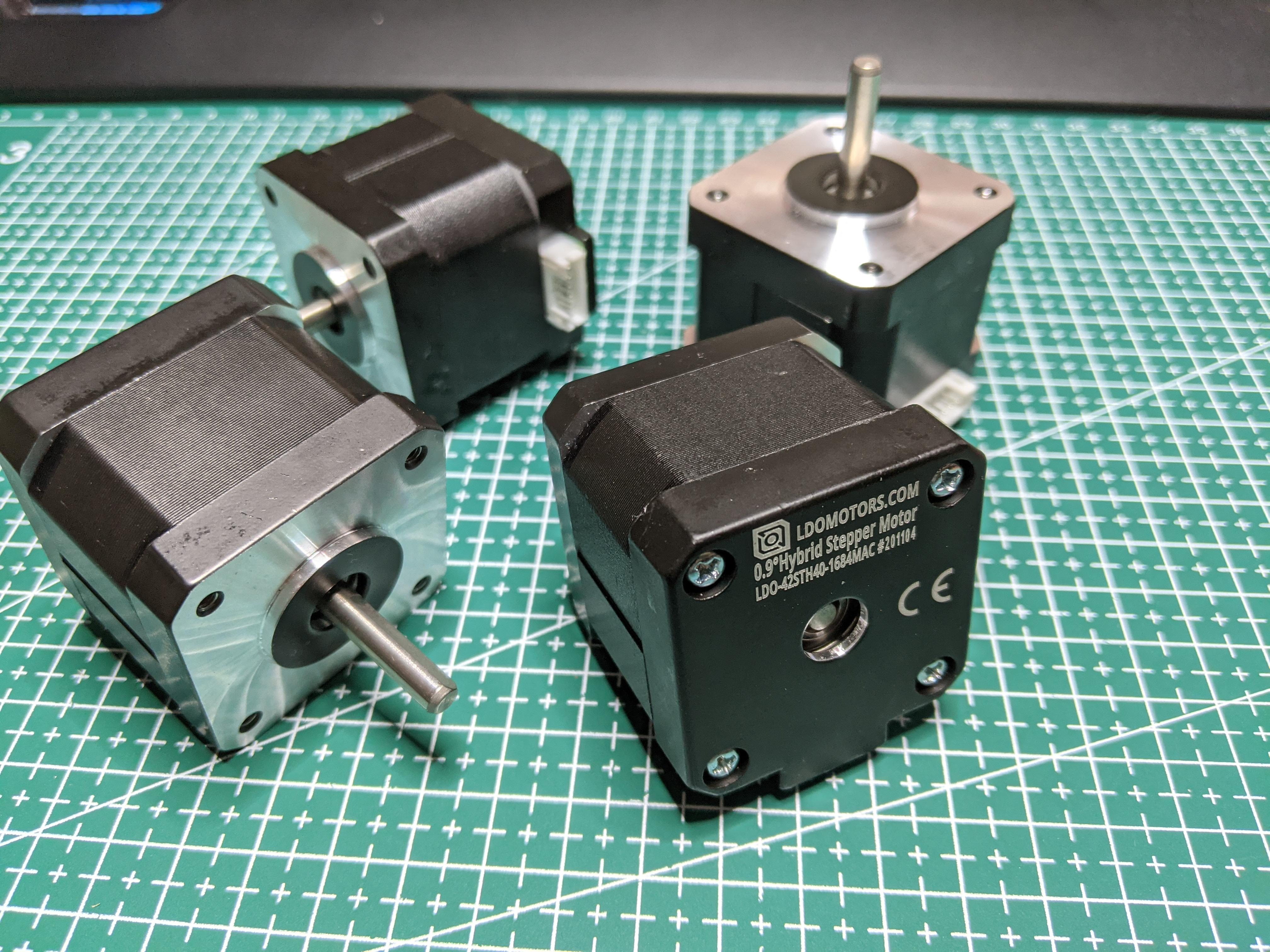
Photo Courtesy : 3D Printing Geek via Reddit
Klipper is an advanced 3D printing firmware that gives you a high level of control over how your 3D printer moves. One key part of this control is the measurement and management of your stepper motor's motion. Klipper does this with the help of the Rotation Distance parameter.
Rotation Distance measures how far your print head moves in a single rotation.This value has an impact on the dimensional accuracy and appearance of your prints. and, in turn, is a key factor in determining the final quality of your 3D models.
In this article, we'll talk about what the rotation distance means in Klipper and how you can use it to get the best prints possible. We'll talk about it in detail and go over the steps for setting up the rotation distance for your 3D printer.
Read on to learn how to 3D print highly accurate parts and take your printing to the next level.
What is Rotation Distance?
Photo courtesy : Jahobr, CC0, via Wikimedia Commons
The Rotation Distance parameter in Klipper indicates the distance an axis moves during one complete rotation of the stepper motor. This value is carefully calculated by taking into account numerous parameters such as stepper motor features, extruder gearing ratio (if any), and hardware components.
Consider a case where the gcode command tells the extruder motor to push out 50 mm of filament. But, in reality, it's either 30 mm or 70 mm. This clearly shows a case of under-extrusion or over-extrusion.
In another case, suppose you tell your X-stepper motor to move 100 mm. Instead, it advances 102 mm. Even though this distance might not seem like much, it can be magnified in larger prints. These difficulties have a detrimental impact on your print quality, resulting in sloppy prints with the wrong dimensions.
The rotation distance option ensures that the stepper motor moves exactly as the gcode file commands. Not more, not less. Extruded filament measuring precisely 50 mm.
By correctly configuring the rotation distance value, you can ensure that the prints come out as desired. It will help you fix extrusion problems and improve the quality of your prints.
Rotation Distance vs Steps/MM
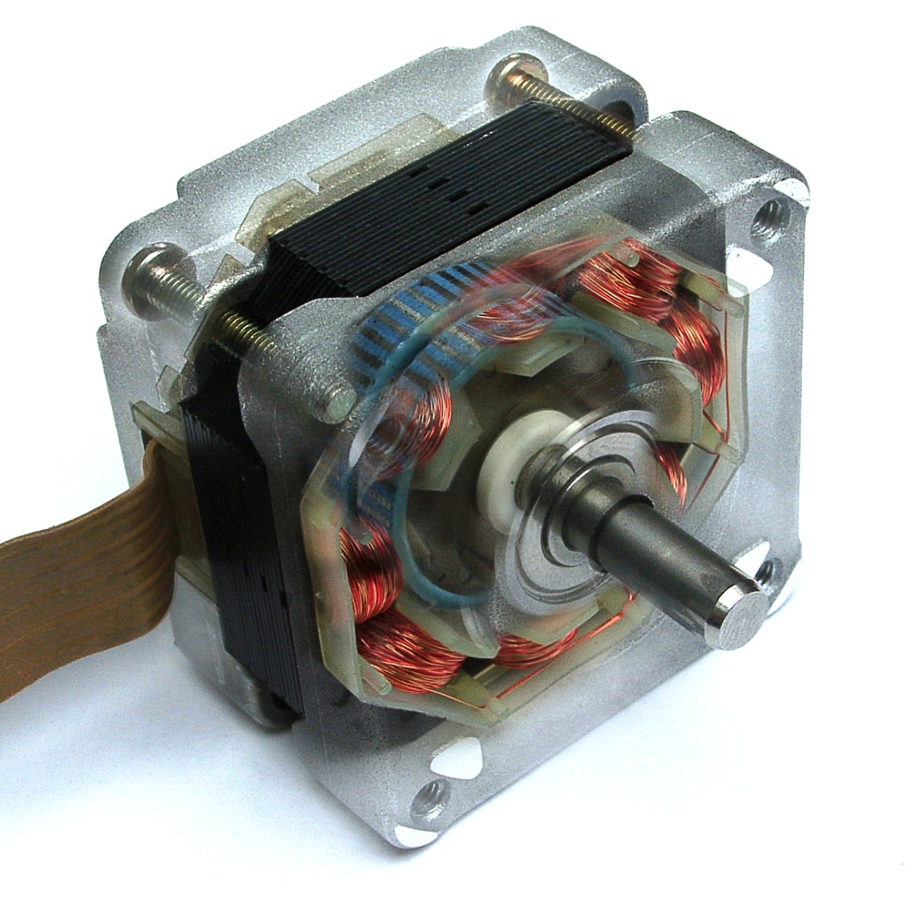
Photo courtesy: Nicolas Kruse via Wikimedia Commons
The accuracy of the motions of your stepper motor is controlled by two parameters: rotation distance and steps per millimeter. Klipper uses "rotation distance," while Marlin firmware uses "step/mm."
The rotation distance is the total distance an axis moves when the stepper motor rotates once. In fact, the circumference of the stepper gear is part of the initial setup for the rotation distance value.
For the extruder motor, just measure the diameter of the gear and multiply it by 3.14. In the case of the X and Y axes, the value is simply the product of the number of teeth on the pulley and the belt pitch. In most cases, this is the actual distance traveled by the print head.
In contrast, the steps/mm option estimates the expected number of steps a stepper motor must take to move 1 mm. It is based on the fundamental assumption that the stepper motor moves linearly.
So, if we specify a value of 80 steps/mm, Marlin assumes that the print head moves 1 mm every 80 steps. However, it does not take into account the printer's actual movement. The accuracy of the prints can be affected if the stepper motor misses steps or is not highly exact.
Overall, both of the parameters are valid and produce great results. Klipper's rotation distance, however, has an advantage due to its simplicity and ease of configuration.
For the initial setup, all you need is information about the printer's hardware. In the next section, we'll explain how to calibrate this rotation distance value.
Setting up Rotation Distance
Klipper's extended Gcodes make adjusting the rotation distance of your stepper motors a breeze. The way the extruder motor and the X, Y, and Z stepper motors are set up is a little different. So, we'll split this part into two separate sections. It will keep things simple and help you better grasp the setup process. Let's rotate.
Extruder Motor
The value of the extruded filament depends on several factors. Filament friction, nozzle pressure, melting temperature, etc. These parameters make it challenging to calibrate the rotation distance parameter and ensure it’s correctly set.
We'll use the measure and trim test for this. This test verifies the extruder motor's extrusion accuracy and ensures that it is extruding the correct amount of filament.
You’ll need to gather the following materials before we begin:
- 3D printing filament
- Vernier caliper or dial gauge.
- Sharpie, permanent marker
- Fluid/Mainsail interface Klipper
Step 1: Load Your Filament
Preheat your hot end to the melting temperature of the filament. Keep the temperature close to your printing temperature. It helps to get actual values that will be useful for your prints.
Ensure the hot end is completely filled with filament. You can verify this by looking for small strings extruding out of the nozzle.
Step 2: Make a mark on the filament
Measure 120 mm from the edge of your extruder on the filament. Mark the point using a Sharpie. It’s our "Initial Mark Distance.”
Step 3: Extrude Filament
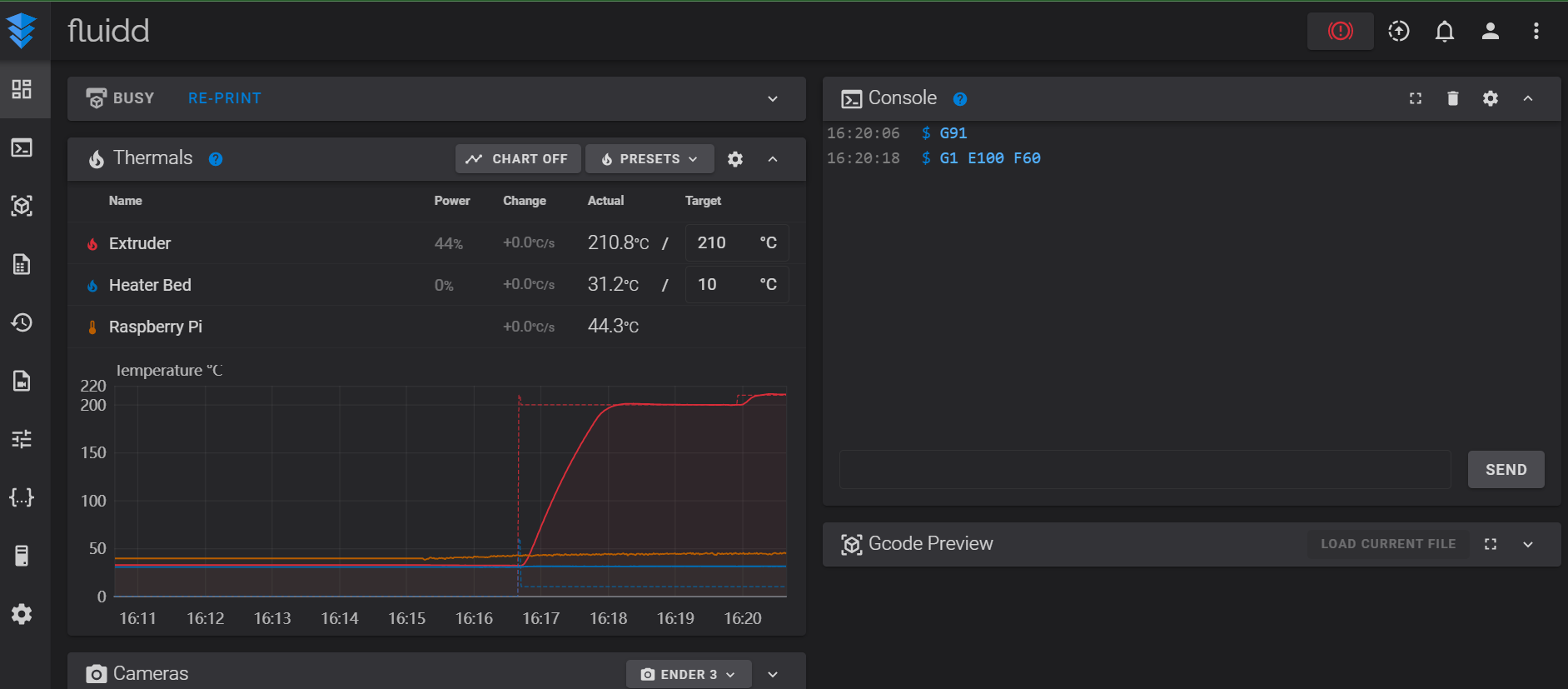
Extrude 100 mm of filament by inputting the following command in the Fluidd/Mainsail terminal. The 100-mm value is our "Requested Extruded Distance."
G91
G1 E100 F60
The filament will start extruding out of the nozzle. It’ll take some time to complete the extrusion process. Slow extrusion speeds ensure that there’s no buildup of pressure inside the nozzle that can skew our results.
Note: Do not use the Extrude button on the Fluidd interface or your LCD display. They extrude at a fast rate and can alter the test results.
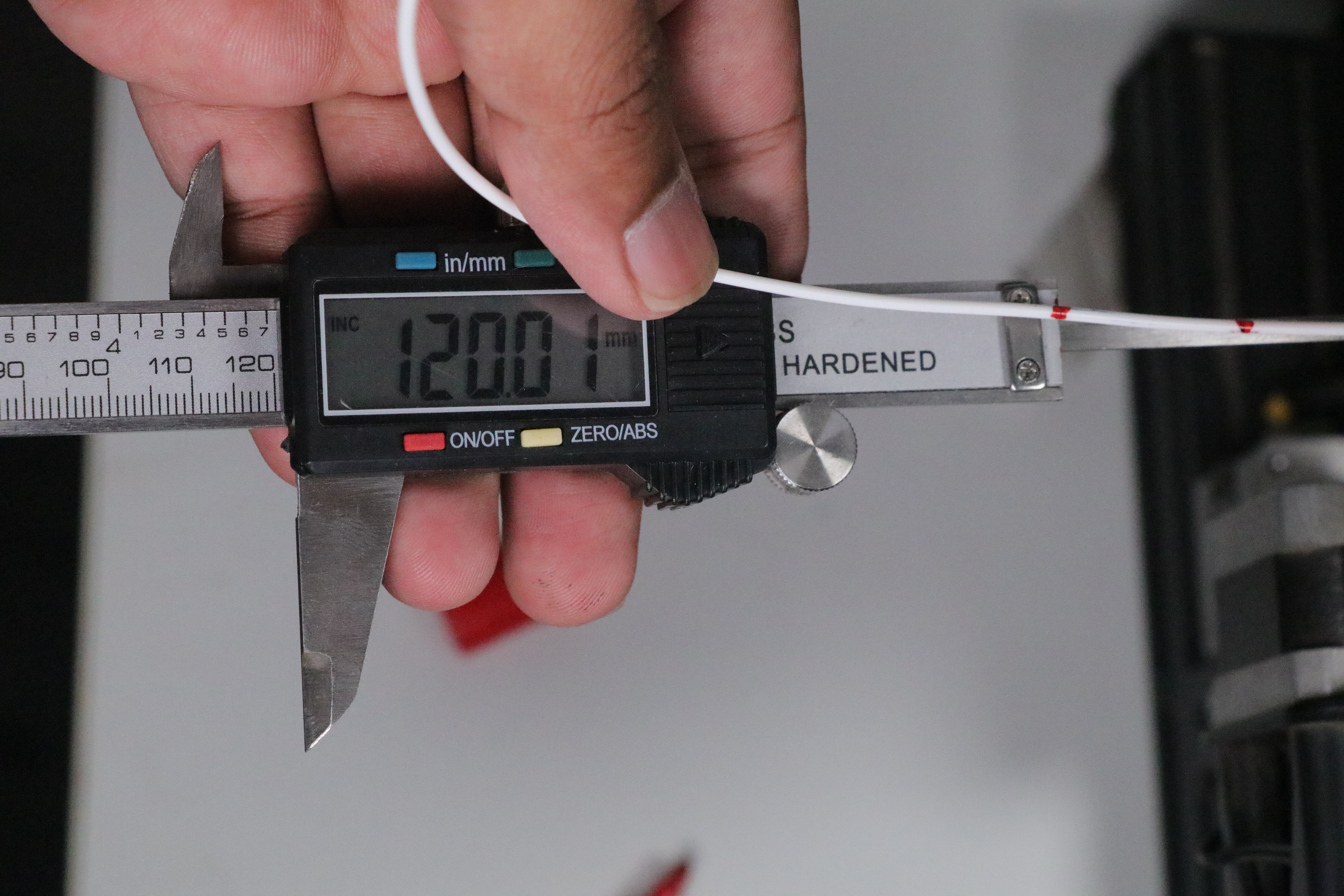
Step 4: Extruded Filament Measurement
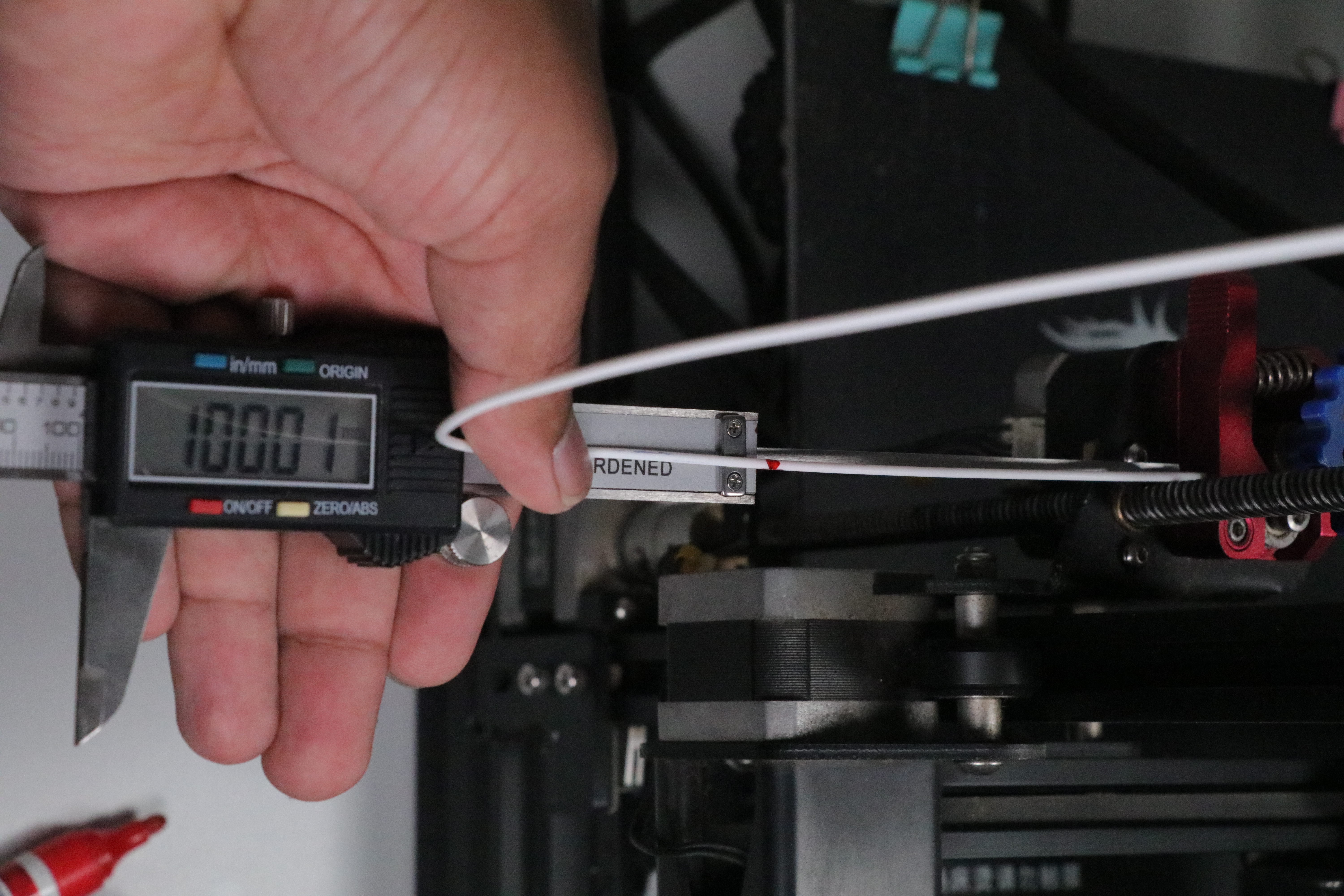 Use the digital vernier calipers and measure the remaining filament from the edge of the extruder to our 120 mm mark. The value denotes your "Subsequent Mark Distance."
If your extruder is over-extruding, it would go beyond the 100 mm mark. Your subsequent mark distance would be less than 20 mm (120 mm - extruder edge distance). On the other hand, if the extruder is under-extruding, this value would be more than 20 mm.
In our case, the 100 mm mark aligned correctly with the extruder edge. So, the actual extrude distance is the same as the initial mark distance.
Use the following formula to get the "Actual Extruded Distance."
actual_extrude_distance = <initial_mark_distance> - <subsequent_mark_distance>
Step 5: Calculate the Rotation Distance
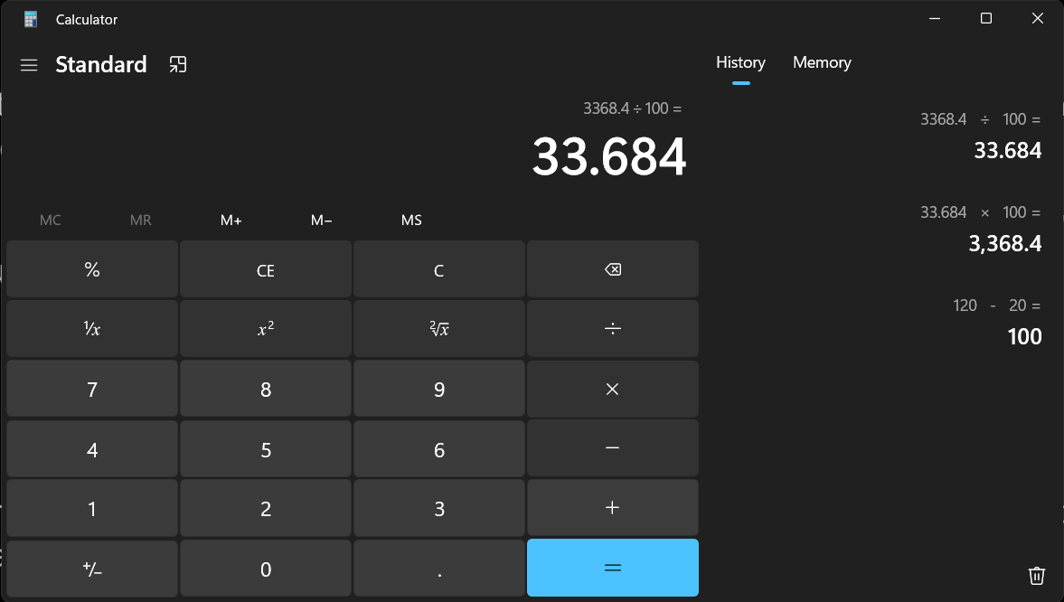
Use the following formula to calculate the rotation distance for your extruder. You can get the previous rotation distance from the printer.cfg file, under the extruder section.
rotation_distance = "previous_rotation_distance" * "actual_extrusion distance" / "requested_extrusion distance"
Step 6: Input the new rotation distance value in Klipper.
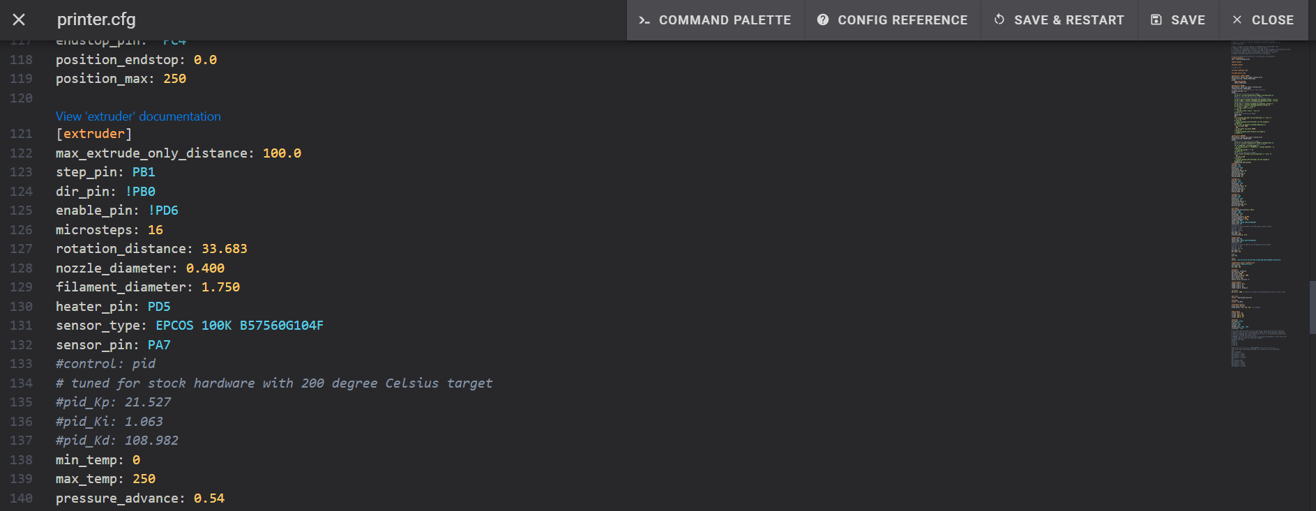
Open your printer.cfg file. Under the extruder section, replace your previous rotation distance value with a new one. Save and restart the firmware.
In case there’s more than a 2 mm gap between the "actual extrude distance" and the "requested extrude distance," it’d be helpful to repeat the procedure again. The goal is to minimize the error.
That’s it! You’ve successfully calibrated the rotation distance value for your extruder motor. You can verify the results by extruding and measuring 100 mm of filament. The extruded filament should be close to the true input value.
Geared Extruders
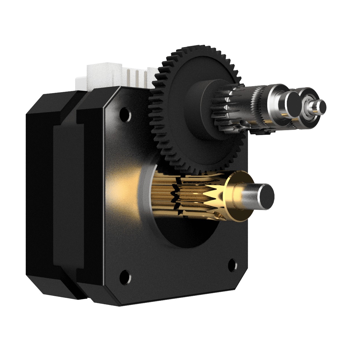
Photo Courtesy: Bondtech
With geared extruders, you need to consider the gearing ratio of your extruder motor and input it in the printer configuration file. If you’re unsure whether you have a geared extruder or not, it’s better to verify before proceeding. Most 3D printers don’t have one.
- Check the gear ratio of your extruder.
- Add a line to the printer.cfg file in the extruder section
gear_ratio: teeth on gear 1; teeth on gear 2
- Save and restart the firmware.
Note: Some extruders, like the BMG ones, advertise their gearing ratio as 3:1. But, in reality, the gear tooth ratio is 50:17. As a result, it is always preferable to enter the actual teeth number rather than the final gearing ratio. It’ll give you better results and help improve the extrusion accuracy of your prints.
X, Y, and Z Motors
Your 3D printer will either feature a combination of belt-pulley and lead screw-driven stepper motors or an all-belt-driven system (Voron printers). We’ll look at the procedure to calculate rotation distance for both of these setups.
Belt-driven axes
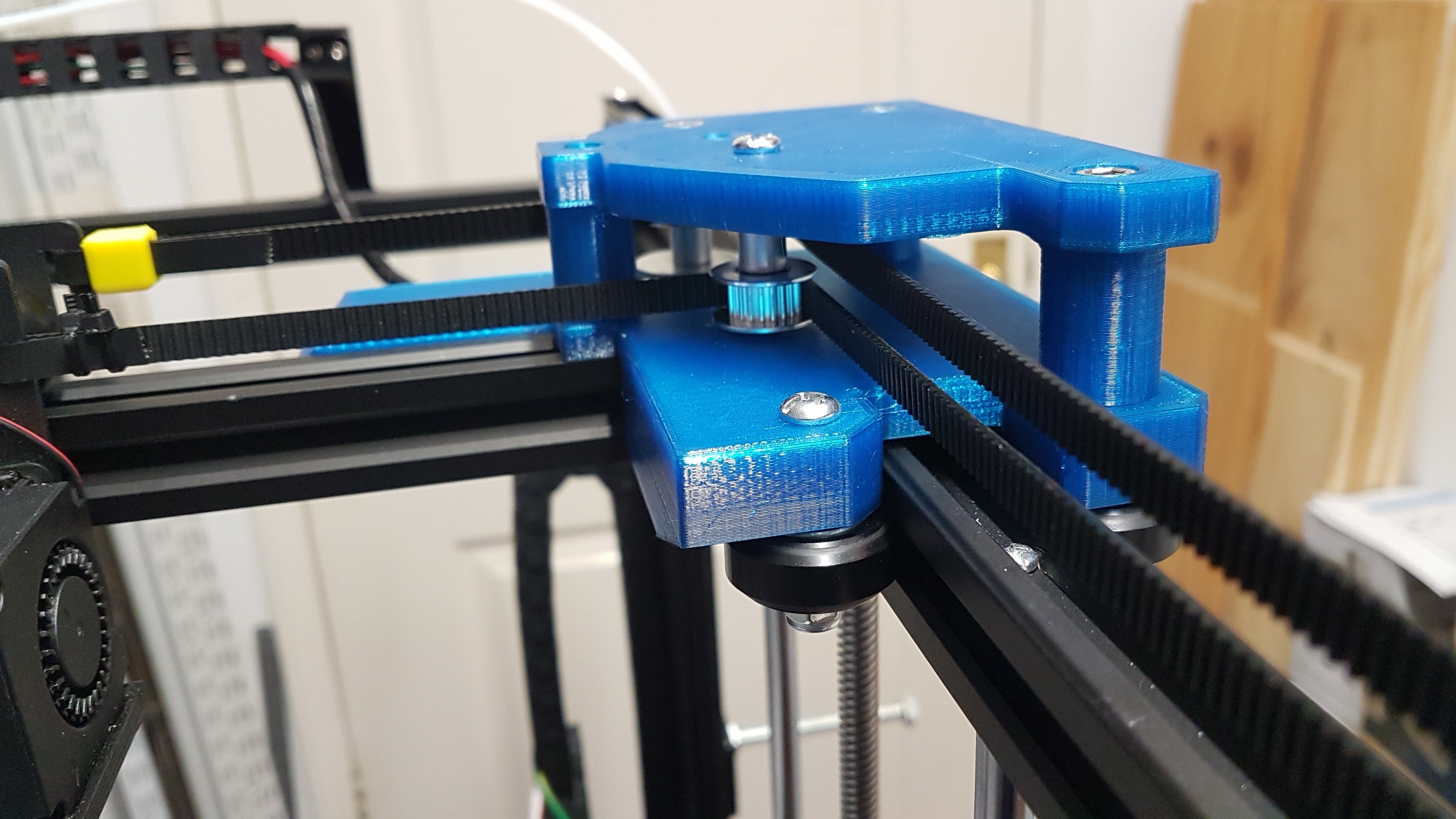
Photo courtesy: GNATTYCOLE via Cults3D
- Check the belt pitch and the number of teeth on your stepper motor pulley. Most 3D printers use a GT-2 belt, indicating a 2 mm belt pitch. The belt pitch is the distance between two consecutive belt teeth.
- Calculate the rotation distance for your stepper motors using the following formula:
rotation_distance = "belt_pitch" * "number_of_teeth_on_pulley" - Home your 3D printer’s axes. Move the belt-driven stepper motors to a set distance. Let’s say 100 mm. Verify this distance is correct by measuring the edge of your print head from the limit switch.
Axes with Lead Screws
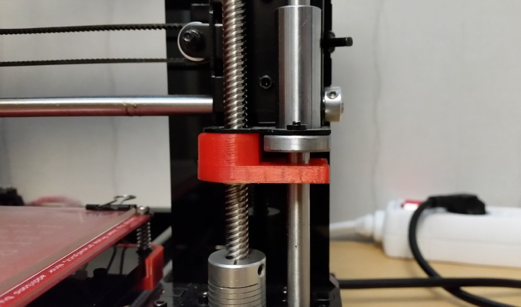
Photo Courtesy : TinyTinker via Thingiverse
- The T8 lead screw is the most commonly used screw on 3D printers. Verify if it’s the same on your printer. If not, check the manufacturer’s website for more details.
- Use the following formula to calculate the rotation distance for your lead screw driven axis:
rotation_distance = "screw_pitch" \* "number_of_separate_threads" - The screw pitch for an T8 lead screw is 2 mm, whereas the number of separate threads is 4. So, the rotation distance is 8.
You have now set the values for how far each stepper motor in your 3D printer can rotate. You can validate these readings by printing a calibration cube. The measurements of the 3D printed model should be close to the real design.
Post Calibration
If your printer continues to create dimensionally inaccurate or under-extruded prints, there might be an underlying problem. Calibrate your flow rate settings and pressure advance values, as well as address any extrusion issues.
You shouldn't need to calibrate the rotation distance parameters unless you're changing your extruder hardware or stepper motors.
Final Thoughts
To sum up, rotation distance is a powerful and versatile tool for accurately measuring the movement of stepper motors in your 3D printers. In contrast to the steps/mm value in the Marlin firmware, rotation distance allows you to measure the actual movement of your 3D printer's stepper motors.
It's also simpler to learn, configure, and update for any hardware changes. This creates a more smooth and user-friendly experience while also boosting the quality of your 3D printing.
Give it a shot with your Klipper 3D printers and let us know how it goes. If you run into any problems, please leave a comment below. We'd be happy to assist you.