3D Printing for Beginners - Terms to Know

The 3D printing world and its terminology can be confusing at times, especially if you are new to 3D printing. We've gathered a collection of 3D printing industry terms and acronyms that you're likely to encounter along the way.
For each term, a small explanation is provided that should help you understand its definition and how it fits in the world of 3D printing.
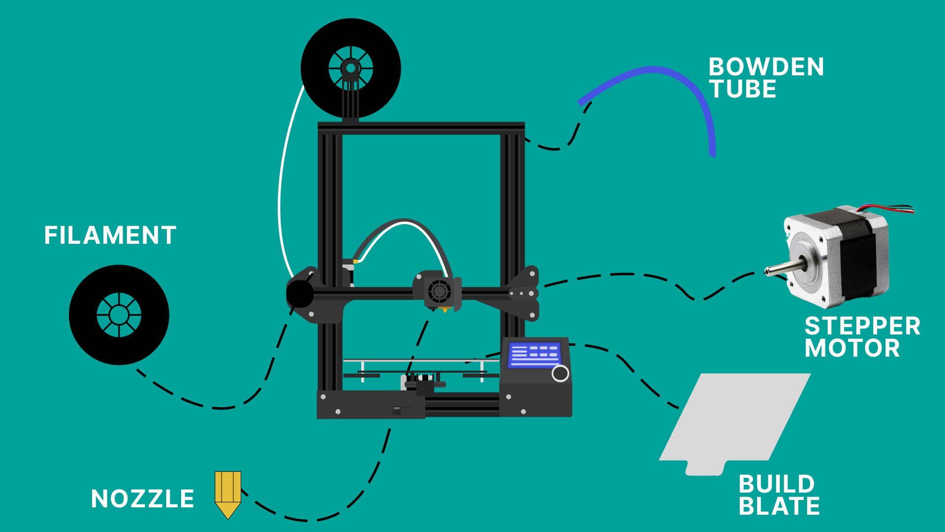
Table of Contents
- Build Plate (Print Bed)
- G-Code
- Infill
- Nozzle
- 3MF
- Filament
- Fused Filament Fabrication (FFF)
- Layer
- Layer Height
- Bed Adhesion
- Brim & Raft
- Slicer
- STL
- CAD
- RepRap
- CoreXY
- Cartesian
- Belt Printer
- Warping
- Z Offset
- Extruder
- Direct Extruder / Direct Drive
- Bowden extruder / Bowden Tube
- Elephant's Foot
- Enclosure
- E-Steps
- PID Tuning
- Flow
- Retraction
- Stringing
- 3D Printer Firmware
- Marlin Firmware
- Klipper Firmware
- Raspberry Pi
- OctoPrint
Build Plate (Print Bed)
The Build Plate, also known as the Build Platform or Print Bed, is a key component of every 3D printer. A build plate's primary function is to provide a perfectly flat, level and mildly sticky surface for the first layer of a 3D print. The first layer is the most critical layer of every print and it can impact the success or failure of a print. So it should perfectly stick to the build plate, otherwise the entire print can fail.
The purpose of the build plate is to ensure the first layer sticks to it and the extruded filament does not warp or curl during the course of the 3D printing operation.
Build plates can be of various materials and surface types like glass, Polyetherimide or PEI coated (smooth and textured types), Garolite, Polypropylene, and others. Additionally, they might be available in flexible and magnetic types, which will enhance your 3D printing experience. In case you are wondering, the build plates can be easily upgraded or replaced.
G-Code
G-code is a programming language that the 3D printer understands and follows. It has a set of commands that the printer follows to carry out the various tasks associated with printing an object. These tasks can include actions like the movement of the printhead, preheating the nozzle, setting extruder and bed temperature, adjusting the print speed, fan speed, layer height, and ultimately stopping the extrusion, switching off heaters, and fans.
The 3D printing workflow basically starts from a 3D CAD file. But a 3D printer does not understand this CAD file, instead this file is then converted into a G-code file via a slicing software and then fed to the 3D printer and the printer performs the various tasks as noted earlier.
Infill
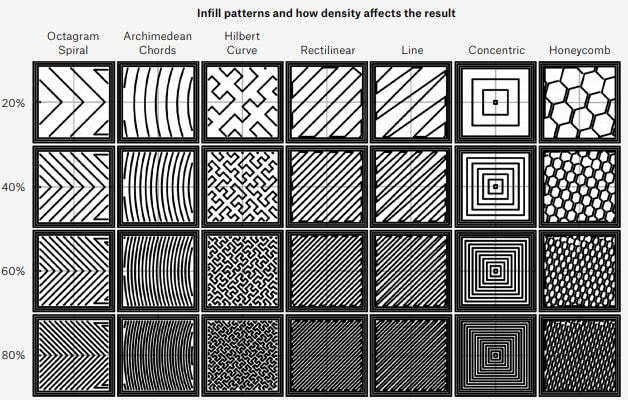
Infill patterns and how density affects the print/ Courtesy: b3d-online
Infill is essentially the internal structure of the print i.e the area within a 3D-printed object that connects top, bottom, and side layers. The density of the infill determines the structure's rigidity and thus the print's durability.
Density is the percentage of how filled the interior of a part is and can range from 0% (hollow) to 100% (solid) or anything in between depending on the desired quality of the final product. Adjusting the infill percentage or the infill pattern for your 3D print can help you save both time and material.
Slicing softwares such as Cura, Slic3r and others offer a variety of different types of infill patterns.
Nozzle
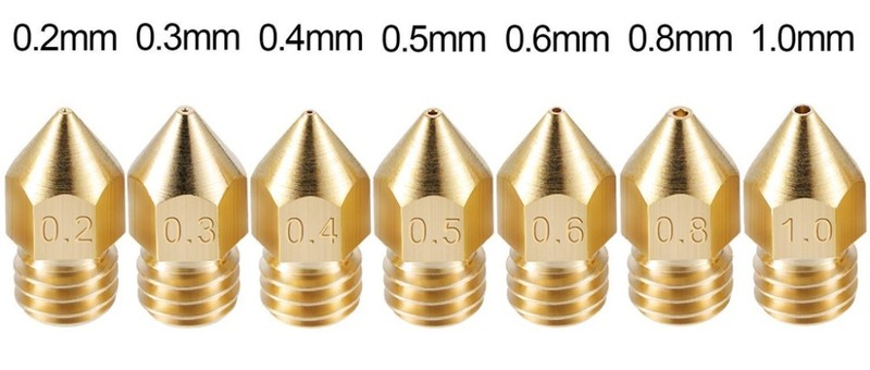
Nozzle diameter sizes/ Courtesy: top3dshop
The nozzle is a mechanical component of a 3D printer in the shape of a funnel through which molten plastic or filament is extruded and deposited onto the build plate to create an object. The nozzle sits inside the printhead of a 3D printer.
Nozzles are available in a variety of diameter sizes (0.1mm, 0.2mm, 0.25mm, 0.4mm, etc.), made in a variety of materials and are used depending on the requirements of the print.
Nozzles are made from brass, brass-Ruby nozzles, stainless steel, hardened steel and others and their selection mainly depends on the materials used. Even the nozzle diameter can influence the quality of print. Knowing about the nozzles will go a long way in improving the print quality.
3MF
3MF, short for 3D Manufacturing Format, is a CAD file format specifically designed for additive manufacturing. This format was introduced in 2015 by the 3MF Consortium, a group of computer software, hardware, and additive manufacturing developers that includes Autodesk, Dassault Systemes, HP, Microsoft, and Ultimaker.
This format was created to address some critical issues with the widely popularized STL file format. The STL file format was inadequate in storing important information about the part to be printed. It can only store external information like surface and shape but is not able to store internal information like structure, color and texture data, etc. The widespread use of the STL format was thought to be causing a slew of compatibility and interoperability issues in the industry.
3MF aimed to be a solution so that more information about a model can be saved in the file while keeping its file size small for faster and easier sharing and uploading. The 3MF format can store more data in one small file including full color and texture support in a single file, support structures attached to part data, full tray support for direct machine preparation, thumbnails, viewing, and printing in Microsoft Windows, and much more.
Filament
Filament is the polymer material used to create objects with an FDM 3D printer. This material is made from thermoplastic polymers extruded in the form of a wire, called filament and is wound upon a spool.
Filaments are materials used only in FDM 3D printing. They are popularly manufactured in two diameter sizes of 1.75mm and 2.85mm.
The popular 3D printing filaments include Polylactic Acid (PLA), Acrylonitrile Butadiene Styrene (ABS), PolyEthylene Terephthalate Glycol-modified (PETG), Polypropylene (PP), Polycarbonate (PC), Nylon, High Impact PolyStyrene (HIPS), and many more. Composite blends of filaments are also available in the form of Metal-fill, Wood-fill, Ceramic-fill, PETG-Carbon Fiber, and others.
Fused Filament Fabrication (FFF)
Fused Filament Fabrication (FFF) is an alternative name for Fused Deposition Modeling (FDM) 3D printing technology. It was made popular during the early years of the RepRap movement to avoid infringing on the Stratasys trademark of FDM. But now it is interchangeably used by all to describe the FDM technology.
The FFF or FDM technology is a material extrusion type of 3D printing technology, as defined by ASTM. In this technology, a polymer material in the form of a filament is melted and extruded via an extrusion system. A nozzle deposits the melted material onto a build platform in a layer-by-layer process one above the other until the entire object is 3D printed.
FFF 3D printers can print with thermoplastic polymers like PLA, ABS, PETG, Nylon, and more.
Layer
You might be aware that 3D printing is a manufacturing technology that builds objects in a layer-by-layer process. Layer, here, is an individual thin slice of the object being printed. In 3D printing, multiple such individual layers are printed on top of one another to form the final object.
The height of individual layers is defined through a parameter called 'layer height' in a slicing software. The job of the slicing software is to slice the entire object to be printed into thin layers so that the printer can print the object.
Layer Height
The layer height of a 3D printed object is the height of each individual slice. Objects are built in 3D printing by laying down thin layers of material one on top of the other in a continuous process until the object is formed, as previously explained. The layer height specifies the height (or thickness) of each individual layer.
The layer height, measured in microns, is an important parameter to control because it can determine the print resolution, the surface finish and printing speeds. The smaller the layer height, the higher the resolution and larger the layer height, the lower the resolution. It's also worth noting that higher resolution means finer details but slower print speeds, and vice versa.
Typical layer heights are 100-400 microns in FDM 3D printing, 25-100 microns in resin 3D printing, 80-150 microns in SLS 3D printing and 30-60 microns in DMLS/SLM 3D printing.
Bed Adhesion
Bed adhesion is the ability of 3D printed plastic to "stick" to the build plate while printing. A good bed adhesion is crucial from the point of view / perspective that if the bed adhesion is poor, then the part being printed can lose contact with the surface and can cause print failure.
It can either warp or curl at the edges or completely move from its place. In any case, the print fails.
Users can safeguard against this through three methods:
Printing Parameters: Users can control printing parameters like the increasing first layer height, switching off fans for initial few layers, using slicer tools like Brim and Raft (read the next section on these tools).
Hardware: Bed adhesion can be improved by using a heated bed and using a heated enclosure.
External Tools: Using external tools like a Kapton tape to increase stickiness of the surface, applying glue (like Magigoo) to the print bed, applying ABS slurry (a mixture of acetone and ABS scraps).
Brim & Raft
A brim is an extended layer of material attached to the outer surface of the object but only for its first layer. Think of it as the brim of a hat. Its purpose is to increase the surface area of the part being printed and act as a protection from warping and curling.
A raft on the other hand is a thin multi-layered base which acts as a foundation onto which the object is printed, instead of the build plate. The raft also increases the surface area in contact with the print bed and thus safeguards against warping, curling and even losing complete contact with the bed.
Rafts are a better option than brims but it requires additional material which is actually waste.
Slicer
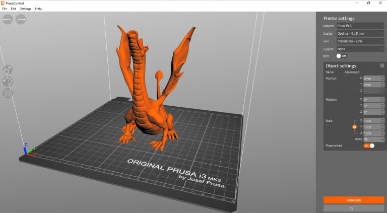
3D printer interface of Prusa Slicer / Courtesy: Prusa
Slicer is a software that slices the CAD model into thin layers or cross-sections that the 3D printer can then print. You must be aware that a 3D printer prints parts in only two-dimensions (X & Y-axis) at a time. Once one layer is printed, the bed moves in the Z-axis and the printer again prints the next layer on top of the previous layer in the X- & Y-axis. In short, the 3D printer prints multiple 2D layers in three dimensions. And these 2D layers are called slices.
A 3D printer can only print these slices and the software that converts the CAD model into thin slices is a Slicing software, or Slicer. The Slicer takes input of multiple parameters like the layer height, extruder temperature, bed temperature, print speed, infill, support structure, nozzle and bed movement and converts these inputs into a G-code which the 3D printer understands and follows. This G-code is then fed to the 3D printer to print the object.
Prusa Slicer by Josef Prusa, Cura by Ultimaker and Ideamaker by Raise3D are the top slicing software programs.
STL
STL is an abbreviation for Standard Tessellation Language, and it is a file format for 3D models used in 3D printing. When a CAD model is exported to the STL file format, it is easily readable by 3D printing slicing software. However, STL files only retain the geometry of a surface, not its color or texture.
STL format is old in computer terms, having been introduced by 3D systems in 1987 and having several interoperability and ease-of-use difficulties. And that's why alternatives like 3MF and OBJ file formats are becoming more popular.
Nonetheless, it remains the most widely used file format in 3D printing.
Most slicers can import STL files, so if you find a design on the web, it's best to download it in that format.
CAD
Computer Aided Design or CAD is the process of digitally designing 3D models. 3D printing always begins with a CAD design, regardless of the 3D printing technology being used.
Typically, there are three different CAD modeling techniques: Wireframe modeling, Surface modeling, and Solid modeling. Solid modeling is most commonly associated with 3D printing since they are parametric and ideal for designing a wide range of real-world objects and products.
There are many different CAD programs available for all budgets and skill levels. Web-based Tinkercad is ideal for beginners, Autodesk's Fusion 360, Rhino, and others are suitable for intermediate users, and Catia, SolidWorks, PTC Creo, and others are ideal for advanced users due to their advanced features and tools.
RepRap
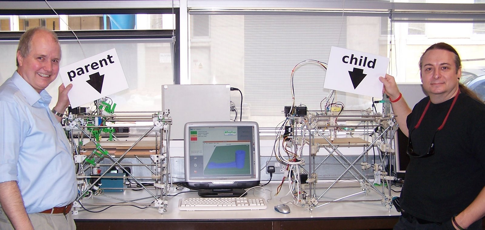
Adrian Bowyer (left) and Vik Olliver (right) with a parent RepRap machine and the first complete working child RepRap machine/ Courtesy: RepRap
RepRap is an open source 3D printing initiative founded in 2005 by the University of Bath to develop low-cost, open-source, and mainly self-replicating 3D printers.
The "Replicating Rapid Prototyper" (or "RepRap") project was highly successful, leading to the development of a lot of machines such as the RepRap Mendel and has been the catalyst for the rise of companies like Prusa, Ultimaker and MakerBot.
In addition to achieving its goal, the RepRap project contributed directly to a boom in 3D printing. It started a revolution that saw the fall in prices of the FDM 3D printers leading to the proliferation and democratization of the 3D printing technology. Today, the term "RepRap" is commonly used to refer to a wide range of things that were inspired by or developed as a result of the project.
As an open source initiative, each of its designs is made publicly available under a free software license.
CoreXY
The term CoreXY refers to a particular design motion system on 3D printers. In the CoreXY based motion system, the printhead moves in the X- and Y-axis using one stepper motor each while the bed only moves in the vertical Z-axis. Due to this design, all the stepper motors are fixed and remain stationary at all times.
The design has several advantages over its counterparts like reduced vibrations, reduced moving parts, reduced potential of print failure and achieving higher print speeds among others.
All popular 3D printers like those from Ultimaker, Prusa, and many others use a CoreXY motion system.
Cartesian
Cartesian 3D printers are the most popular FDM 3D printers on the market today. The technology is based on the cartesian coordinate system, which employs three axes, X, Y, and Z, to calculate the proper position and direction of the print head. The stepper motors drive the print head and the build plate along these rails so that the object can be printed in the exact dimensions specified by the 3D model.
Rene Decartes devised the Cartesian coordinate system, which bears his name.
Belt Printer
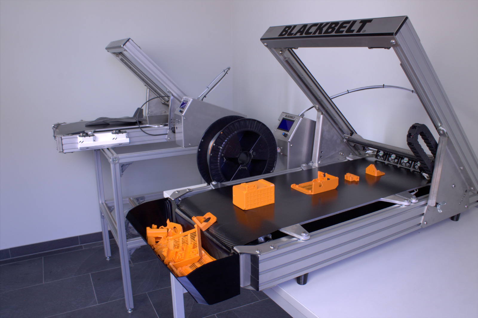
The belt's basket collects parts as the machine prints / Courtesy: 3dprintingindustry
Belt 3D printers are essentially Cartesian-XY-head printers or CoreXY printers with a 45-degree tilt that employ a big moving belt instead of a print bed.
Using a conveyor belt as a bed allows you to 3D print continuously, whether you want to make several regular-sized models or one really long part. The downside is that belt 3D printers have limited speed and cannot work with filaments that demand a high-temperature heated bed.
Belt 3D printers are still in their early stages. The first generation, the Blackbelt printer, came out in 2017.
Warping
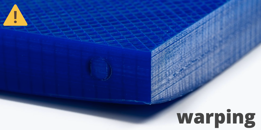
Warped bottom corners / Courtesy: wikifactory
Warping occurs when the corners of a 3D print come loose from the build plate and the base curls up. In the technical sense, warping is the thermal contraction of material when it cools down due to variations in temperatures between layers.
Warping can be avoided by using a heated bed, which keeps the first layer of the print hot enough to keep it glued to the bed.
Other methods for preventing warping include regulating the ambient temperature (via an enclosure), using a brim or raft, or spraying glue or hairspray on the print bed.
Z Offset
The Z offset is the distance between the hot end or nozzle and the Z home position. This setting must be calibrated in order to achieve the perfect first layer.
In some cases, such as when using filament with poor adhesion or when using a thick build surface, adjusting the Z offset of the 3D printer is the key to getting good results.
You can adjust the Z Offset by modifying the G-Code or directly entering an offset in a slicer.
Extruder
An extruder is a motor equipped with gears that pushes filament towards or away from the hot end of the printer. The movement is controlled by a set of two gears rotating in opposite directions. The extruder is an incredibly important part of your 3D printer because it controls how much filament goes through the hot end. Your extruder can be set up in two ways: Direct or Bowden.
Direct Extruder / Direct Drive
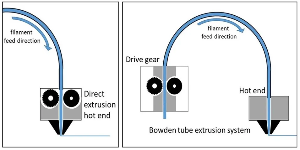
Direct Extruder or Direct Drive / Courtesy: manufactur3dmag
In Direct Extruder or the Direct Drive, the extruder is on the print head, right above the hot end. In this setup, the filament passes directly from the cold end to the hot end.
The shorter distance between the drive mechanism and the hot end can ease printing with flexible materials such as TPU. The gap between the extruder and the hot end (or the tube inside the hot end) tends to be smaller, reducing the likelihood of filament bunching.
Bowden extruder / Bowden Tube
In the Bowden extruder, the hot end and cold end are not directly attached to each other. Instead, they are connected by a Bowden tube that goes from the extruder to the hot end.
The most common weakness of Bowden extruder is that it is prone to issues dealing with retraction, stringing, and lag. Most low-cost printers on the market today use a Bowden setup, which works well for most applications. However, Bowden extruder is not the best option due to its limitations in the use of flexible or abrasive materials.
Elephant's Foot
An illustration of Elephant's foot / Courtesy: pick3dprinter
Elephant's foot is a problem in which the first layer (or first few layers) are wider than intended. It's caused by excessive weight of successive layers on the first layer. If the first layer is not properly cooled and remains in a slightly fluidic state then it starts to spread outwards thus causing the elephant foot problem. This is why the problem is most noticeable in large prints.
Re-leveling the bed and adjusting the first layer settings are straightforward fixes. In other instances, lowering the print bed temperature and tweaking the cooling fan should solve the issue. Printing your part on a raft is a foolproof solution.
Enclosure
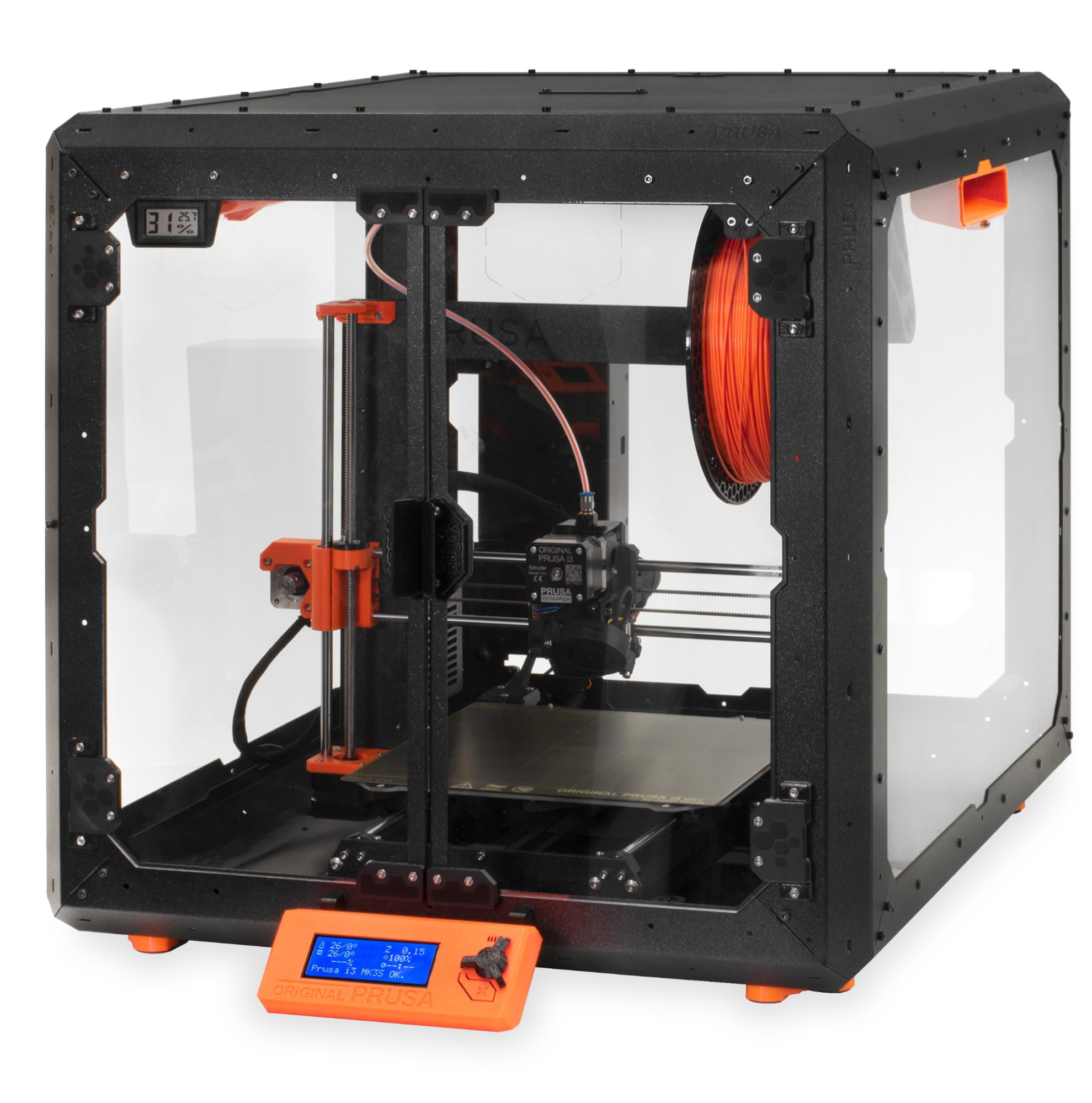
Original Prusa Enclosure / Courtesy: Prusa
An enclosure for a 3D printer is a box or crate that completely encloses the printer and maintains a stable temperature inside. Although a 3D printer enclosure isn't necessarily a must-have in your 3D printer, the controlled environment in and around a 3D printer reduces the common 3D printing issue of warping. For accurate printing on some materials, such as ABS or ASA, an enclosure is necessary.
E-Steps
E-steps are the number of steps required by a stepper motor to extrude one millimeter of filament. The "E" stands for the extruder, and "step" stands for the steps of the stepper motor in the extruder.
If your E-Steps are not properly configured, your prints may suffer from over extrusion and sag.
Even if the brand new 3D printer is factory calibrated, it will lose accuracy over time as parts wear out and the filament extruded by the printer and the steps performed by the stepper motor may not be in sync and precise.
So, an E-step calibration is needed every so often to fix problems with too much or too little extrusion.
PID Tuning
PID tuning is a method of calibration that ensures the printer never deviates from the set temperature. PID is an abbreviation for Proportional, Integral, and Derivative. A 3D printer with a heated bed has two heating components: the nozzle and the bed. The machine's firmware takes three inputs (P, I, and D) and uses an algorithm to determine the best way to keep the heat ratio constant by integrating the recorded error and modulating the speed according to the derivative.
If your printer's temperature consistently fluctuates by a few degrees above and below the set number, it likely needs PID tuning.
Flow
Flow is the continuous motion of a filament. It is calculated by the 3D printer using the diameter of the filament as well as the exit diameter of the nozzle.
The volume or flow of filament that goes through the extruder to create a 3D model is determined by the user's settings. Changing the flow rate directly affects how much plastic is extruded, which in turn affects the layer heights and total print weight.
Retraction
Retraction is the backward movement of an extruder motor to lessen the quantity of material stringing or leaking. When you hear backwards rotation and notice filament being pulled back, that's retraction.
If there is too little retraction, then it will form faint threads or "strings" of material sticking across your model. If there is too much retraction, then you will probably get blobs all over your model.
Retraction settings can be adjusted in the slicer software.
Stringing

Stringing vs. good print / Courtesy: 3dsage
Stringing occurs when little plastic strings are left behind on a 3D printed object. This is usually caused by filament dripping from the nozzle as the extruder moves to a new spot. Simply put, stringing is caused by over-extrusion.
These strings can usually be removed after printing with a hairdryer or other 'heat instruments,' but they are still an annoyance.
The quick fix is to check the Retraction settings, which control the filament to be pulled back into the nozzle after the extruder is done printing one part of the object.
3D Printer Firmware
Firmware is just software that runs on a device's hardware. In a 3D printer, when a user sends a G-code file from their slicing software to their 3D printer, the firmware "works out" the code and sends the appropriate signals to the printer's components, such as the stepper motors, heaters, display, and so on.
Marlin firmware is the most widely used firmware. If Marlin does not satisfy your requirements, additional choices like Klipper, Repetier, SmoothieWare, and others can be tried.
Marlin Firmware
Marlin is open source 3D printer firmware primarily designed for RepRap project based FDM 3D-printers using the Arduino platform. The majority of FDM 3D printers use the Marlin firmware, making it the industry standard.
One of the primary reasons why Marlin remains the number one choice among 3D printing enthusiasts is its strong community support.
Klipper Firmware
Klipper is an open-source 3D printer firmware developed by Kevin O'Connor that combines the capabilities of a general-purpose computer with one or more microcontrollers. Klipper does what 3D printer firmware is supposed to do: it allows 3D printer hardware, such as motors and sensors, to interact with software, such as slicers, to execute G-Code commands.
But, with its slightly different approach to processing G-Code commands, Klipper does it better and faster.
Raspberry Pi

Raspberry Pi 3 Model B Courtesy: Raspberry Pi
Raspberry Pi's are credit card-sized, super-cheap computers that are technically known as single-board computers (SBC). Raspberry Pi's have a wide range of potential applications, including as music players, web servers, and console emulators.
In 3D printing, a Raspberry Pi is often used as a secondary board to run software like OctoPrint. Raspberry Pi has always cost less than $100 (usually around $35 USD), and its cheapest model, the Pi Zero, costs just $5.
OctoPrint

Web interface for OctoPrint / Courtesy: helpnetsecurity
OctoPrint is a brilliant web interface for your 3D printer that lets you control and monitor all aspects of your printer and print jobs directly from your browser.
OctoPrint plug-ins take this very useful tool to a whole new level by giving you custom features and add-ons that enhance the user's 3D printing experience. You can access a plethora of useful capabilities, such as 3D Printer Status Notifications, wireless 3D printing, webcam monitoring of your 3D printer, detecting print failures, the ability to monitor and control multiple 3D printers, and more.